Installing a 4 inch (DN100) wafer butterfly valve without damaging its seat is mainly a matter of controlling contact. Isolate, drain, and depressurize the line; clean the flanges and bore; support the pipe; keep the disc in the specified position; tighten evenly; and prove free travel before testing.
img.butterfly-valve.webp
Start with a Clean, Supported Installation
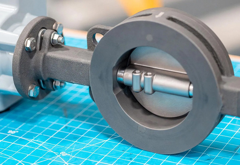
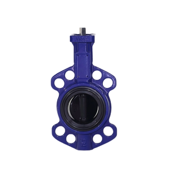
Begin with the valve tag, model drawing, seat material, pressure class, and flange standard in front of the crew. ET VALVE’s wafer-type soft-seated butterfly valve range includes DN40-DN1200 sizes and several seat and actuation choices; installation details remain model-specific.
Before lifting the valve into the gap:
Lock out the line, drain it, and confirm zero differential pressure.
Inspect the seat lip and disc edge for cuts, rolled sections, or transport damage.
Remove weld spatter, scale, grit, and sharp projections from both pipe bores.
Check that the flange faces, bolt pattern, face-to-face gap, and pipe ID match the drawing.
Confirm pipe supports carry the load; the valve must not correct sag or offset.
Verify the supplied sealing-surface or gasket arrangement.
The first hold point is simple: if the flanges are not clean, parallel, concentric, and independently supported, do not insert the valve yet.
img.wafer-butterfly-valve-soft-seat.webp
Why Does Flange Alignment Protect the Seat?
A wafer valve has little room to absorb an installation error. An angular flange can press one quadrant of the seat harder than the other, while an offset pipe can force the disc edge to rub the liner. Either condition may create a leak path or permanent witness mark.
Check the flange faces with a straightedge or approved alignment method. They should be parallel, correctly separated, and centered on the same pipe axis, with no bore step to catch the disc. Use supports, jacks, or permitted alignment tools. Do not use valve bolts to pull a badly aligned joint together.
For general context on disc movement, shutoff, and operating limits, review the butterfly valve operating basics before finalizing the installation method.
How Should the Valve Be Positioned Before Bolting?
With the flanges clean and supported, bring the valve into the gap without dragging its seat across either face. Lift from the body or approved lifting points, not from a handwheel, actuator, switch box, or stem. Keep temporary alignment bolts loose enough to center the body.
Set the Disc Position for Insertion
Follow the supplied drawing for the temporary disc angle. Many wafer designs call for the disc to be slightly open during insertion so the edge remains inside the body and cannot catch the flange. Do not assume that fully closed is safe, and do not rotate the disc against a stop to make the valve fit. If an actuator is fitted, use its approved manual override or the specified hand control. Keep hands and tools clear of the disc edge while the body is being centered.
Keep Tools, Gaskets, and Debris Away from the Seat
Keep bolt threads, flange corners, weld beads, stones, and sharp gasket projections out of the bore. Never pry against the resilient seat or drag the valve across a flange face. A gasket is not automatically required for every wafer design. If the product uses an integrated sealing surface, adding a generic gasket can change the compression or place material in the disc path. Use only the arrangement stated in the model documentation.
What Is the Correct Bolt-Tightening Sequence?
Once the body is centered and the disc edge is clear, install the specified bolts and nuts and tighten them by hand. Confirm that the valve has not shifted toward one flange. Then use a calibrated tool and a diagonal or star pattern in several passes:
Snug opposite bolts in a cross pattern.
Check the body remains centered and the gap remains even.
Increase torque in the number of passes required by the project or manufacturer.
Stop at the specified value; do not substitute actuator torque or a cheater bar.
Stroke the isolated valve slowly after initial snugging and again at final torque.
Uneven loading can pinch one side of a soft seat, distort the body, or raise operating torque. Never invent a torque value from bolt size alone; use the value for the valve, flange, fastener, gasket arrangement, and procedure.
How Do You Check Disc Clearance and Seat Compression?
Treat mechanical inspection as a hold point before pressure testing.
Check
Accept When
Stop and Correct When
Seat and disc visual inspection
No cuts, folds, foreign material, or transport damage
A lip is rolled, torn, or trapped between faces
Body centering
Flange gap and bolt engagement are even
The body is visibly offset or being pulled sideways
Disc-edge clearance
The disc clears the pipe, liner, and flange at slow travel
Any scrape, catch, or contact mark appears
Full travel
The disc reaches the specified open and closed stops smoothly
Torque rises suddenly or the actuator stalls
Stem and actuator alignment
The operator is supported and accessible
The actuator is carrying pipe strain or side load
Bore cleanliness
No grit, weld slag, or loose coating remains
Debris can be seen or heard moving through the bore
A free mechanical stroke does not prove pressure tightness. Hydrostatic or pneumatic testing must follow the valve rating, test medium, direction, and project procedure. Keep personnel clear during any pressurized test.
Which Installation Mistakes Damage a Wafer Valve Seat?
Five shortcuts account for many avoidable failures:
Pulling misaligned flanges together with bolts: realign and support the pipe first.
Inserting the valve fully closed: use the model-specified insertion position so the disc edge stays protected.
Leaving weld spatter or grit in the bore: clean and inspect before the valve enters the gap.
Adding an unapproved gasket: confirm the seat and flange arrangement from the drawing.
Stroking against debris or high differential pressure: isolate the line and remove the obstruction before operating.
Seat material and service also matter. ET VALVE’s wafer-type rubber-lined butterfly valve is a different construction from a detachable soft seat, so its handling and inspection instructions should be followed as supplied. Installation guidance should also reflect whether the duty is isolation or repeated modulation; the distinction is covered in isolation versus throttling service.
FAQ
Resolve these edge cases before the crew signs the hold point.
Should the Disc Be Fully Closed During Installation?
No. Follow the model drawing, which commonly calls for a slightly open disc so the edge stays inside the body and away from the flange. Never force the disc against the seat or a stop to make insertion easier.
Do Wafer Butterfly Valves Need Separate Flange Gaskets?
Only when the valve design and manufacturer specify them. Confirm the exact seat and flange arrangement. An unapproved gasket can fold into the bore, reduce clearance, or change the intended seat compression.
Can Bolts Be Used to Pull Misaligned Flanges Together?
No. Correct the pipe supports, gap, parallelism, and concentricity first. Bolts should clamp an aligned joint, not bend the valve body into position or compress one side of the seat.
How Do I Know If the Seat Was Damaged Before Testing?
Look for cuts, rolled edges, pinches, or uneven witness marks. Then stroke the isolated valve slowly and check for rubbing or abnormal torque. Pressure testing still requires the approved procedure and safe exclusion zone.
What Should I Send for an Installation Review?
Send the valve tag or model, DN/NPS, flange standard, seat material, piping drawing, medium, pressure and temperature, orientation, actuator details, available clearance, and site photos of the flanges and bore.
What Should You Send for an Installation Review?
For a model-specific check, send ET VALVE the installation drawing and valve data before work starts. Include valve identification, flange and pipe details, operating envelope, materials, actuator, orientation, test plan, and photos so the sequence matches the configuration.
Más Información